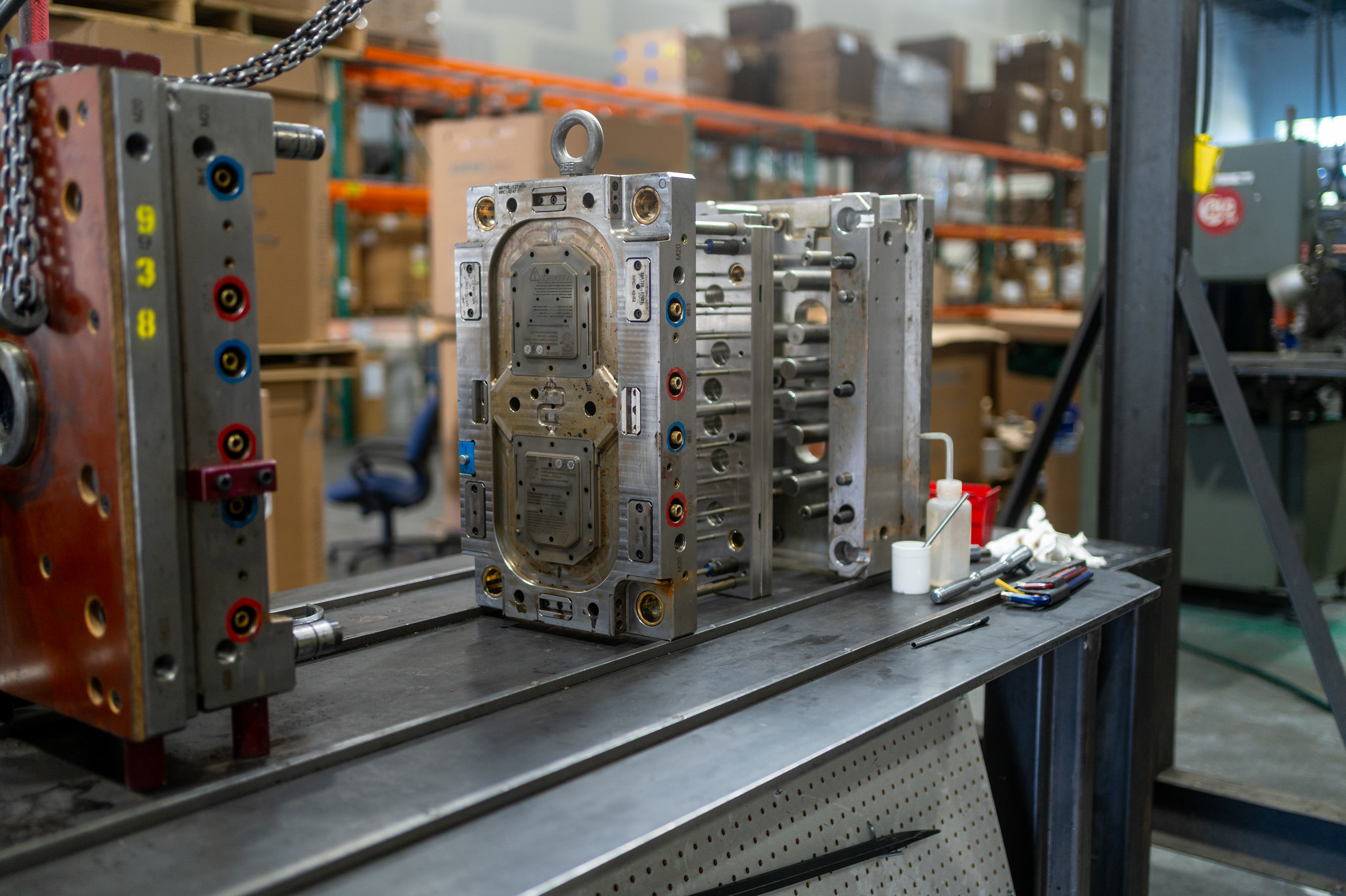
What Is 3K Injection Molding? How Three-Material Parts Are Made
Ever wonder how one button can feel hard on the outside but soft where you grip it? The symbol might even be a different color. No glue holds these parts…

You open a sample box from your molder. The parts look off. One has a line running down the face. Another has a dent that wasn’t in the CAD. A third didn’t fill all the way. What happened, and whose problem is it?
This guide walks you through the seven most common defects you’ll see in plastic parts, what causes each one, and how a quality plastic molding service stops them before they reach your dock. We’ll start with defects you can spot by eye, move into the ones that show up under stress or tolerance checks, and close with the process and design controls a good molder uses to stop defects upstream.
The seven most common plastic injection molding defects are flow lines, sink marks, surface delamination, weld lines, short shots, warping, and jetting. Most are caused by issues with melt temperature, injection pressure, cooling time, mold design, or material contamination.
A quality plastic molding service prevents them through proper DFM review, process validation, and in-process quality control.
A plastic molding defect is any flaw in a finished part that affects how it looks, fits, works, or holds up under stress. Some you can see right away. Others only show up during assembly or in the field.
Defects tend to fall into three groups:
Almost every defect traces back to one of four root causes: the material, the mold design, the process settings, or the part design itself. The good news is that most of them are preventable with the right engineering up front.
At our North Logan shop, we catch the majority of these issues during DFM review and process validation, long before a single production part ships.
Flow lines are wavy patterns, streaks, or faint rings on the surface of a part, usually near the gate. They’re a cosmetic defect, not a structural one, but they can kill the look of a visible component fast.
The root cause is molten plastic cooling unevenly as it moves through the mold. When the melt slows down or cools too quickly in certain spots, you see the path it took.
Common fixes include:
Sometimes flow lines point to a design problem, like a gate placed in the wrong spot. Other times the mold is fine and the process just needs tuning. A good molder uses scientific molding to dial in the right settings before production starts, so you’re not chasing flow lines shot after shot.
At a glance
Sink marks are small dimples or depressions on the surface of a part, usually over ribs, bosses, or thick wall sections. They’re cosmetic, but on a visible part they stand out and often get rejected on first inspection.
The root cause is simple physics. The inner material of a thick section cools and shrinks faster than the outer skin, pulling the surface inward.
You can fix sink marks two ways: through design or through process.
Design fixes:
Process fixes:
When we review a part in DFM, rib and wall geometry is one of the first things we check. Fixing a sink mark in CAD costs nothing. Fixing it after the steel is cut is a different story.
At a glance
Surface delamination shows up as thin, flaky layers that peel away from the part surface, almost like the skin is lifting off. It looks cosmetic at first glance. It isn’t. A delaminated part is a weak part, and it can fail in the field.
The root cause is almost always contamination. That usually means one of three things:
Moisture is the most common culprit, especially with hygroscopic resins like nylon, polycarbonate, and ABS. These materials pull water straight out of the air. If they aren’t dried before molding, the water turns to steam inside the barrel. That steam causes surface streaking, layering, and in some resins it breaks down the polymer itself, weakening the finished part.
Delamination is rarely a machine problem. It’s a material handling problem. That’s why controlled drying, sealed resin storage, and strict regrind rules matter.
We run our material handling under an ISO 9001:2015 quality system, so resin is tracked, dried, and verified before it ever hits the press.
At a glance
Weld lines are thin, visible lines on a part where two flow fronts of melted plastic meet and fuse. You’ll see them most often on parts with multiple gates, holes, or inserts. Some people call them knit lines. Same defect, different name.
The root cause is melt streams cooling too much before they fully bond. When the two fronts meet, they knit together on the surface but never truly weld.
Weld lines aren’t just cosmetic. They’re a mechanical risk. Weld line strength often runs between 50% and 90% of the base material, depending on temperature, pressure, gate layout, and filler content. In fiber-reinforced resins, the drop can be even steeper. On a structural part, that gap can mean the difference between passing and failing.
Common fixes include:
This defect almost always starts at the design stage. By the time you see a weld line on a production part, the mold has already committed to it. That’s why we flag weld line risk before any steel gets cut. When a gate does need to be modified after the tool is built, EDM machining is the process we use to reshape it with precision.
At a glance
A short shot is exactly what it sounds like. The part didn’t fully form. Usually the features farthest from the gate are missing, fuzzy, or incomplete. This is the defect buyers see most often on sample runs, and it’s the easiest to diagnose visually.
The root cause is plastic solidifying before it fills the cavity. The melt ran out of pressure, ran out of heat, or ran out of room to escape air.
Common triggers include:
The fixes follow the cause. Check venting first, because a blocked vent can choke a fill even with perfect pressure. From there, raise the shot size, bump up melt temperature, and verify the resin viscosity matches what the data sheet expects.
Short shots are often a gate and venting problem hiding as a process problem. A molder who only chases the pressure dial will miss it.
At a glance
Warping is a dimensional defect. The part twists, bows, or flattens out of spec after it leaves the mold. On parts that need to fit or assemble, warp kills yield fast. A warped housing won’t snap together. A warped bracket won’t bolt flat.
The root cause is uneven cooling or internal stress locked into the part. One section cools faster than another, and the part pulls itself out of shape as it sets.
Wall thickness and cooling line layout matter more here than most people realize. Thick and thin sections on the same part cool at different rates, and that difference bends the part. Cooling lines that are too far from the cavity, or poorly balanced, do the same thing.
Material choice also plays a role. Semi-crystalline resins like nylon, polypropylene, and acetal shrink differently in different directions. That uneven shrinkage adds warp risk on top of everything else.
Common fixes include:
At a glance
Jetting shows up as a worm-like squiggle on the part surface, starting at the gate and trailing into the cavity. It looks like someone drew a thin line of plastic across the face of the part. Cosmetic, but obvious, and almost always a rejection on visible surfaces.
The root cause is melt shooting into the cavity too fast. The plastic jets out of the gate, cools on contact with the cooler mold wall, and solidifies before the rest of the shot catches up. The later melt flows around that first cold stream, leaving the squiggle behind.
Common fixes include:
When melt hits a wall right at the gate, it spreads out and fills evenly. When it shoots into open cavity space, it jets. That’s why gate location matters so much on this one.
Jetting is usually solved in the mold design stage. Once the gate is cut, your options narrow to process tweaks. Another reason DFM review pays for itself before the tool is built.
At a glance
Most defects you see on a finished part trace back to decisions made before the first shot was ever fired. Zoom out from the individual defect list, and almost every flaw falls into one of four root cause categories.
Material. Moisture in the resin, contamination from the hopper, too much regrind, or the wrong grade loaded for the job. Material problems cause delamination, splay, brittleness, and color shifts.
Mold design. Gate location, vent size, cooling channel layout, and draft angles. A mold that vents poorly or cools unevenly will fight you on every run.
Process parameters. Melt temperature, injection speed, hold pressure, and cooling time. These are the dials on the press. Wrong settings cause short shots, flash, sink, and flow lines.
Part design. Uneven wall thickness, sharp corners, insufficient draft, or unsupported ribs. Design choices in CAD drive warp, sink, and weld line problems downstream.
| Root Cause | Defects It Commonly Produces |
| Material | Delamination, splay, brittleness |
| Mold design | Weld lines, jetting, short shots, flash |
| Process parameters | Flow lines, sink marks, short shots |
| Part design | Warping, sink marks, weak weld lines |
Our DFM review pairs SolidWorks part geometry with Mastercam toolpath planning, so we can flag wall, draft, and gate issues before any steel is cut.
Spotting a defect is one thing. Preventing it on the next run is another. Here’s where a quality plastic molding service earns its keep.
Working with a local U.S. molder shortens the feedback loop when something does go wrong. At Freeform Polymers, we keep design, custom mold design and repair, and production under one roof at our North Logan, Utah facility. When a defect shows up, our tool room is down the hall, not across an ocean.
A few clear signs tell you it’s time to bring in a new plastic molding service:
At Freeform Polymers, we handle DFM review, tooling, short-run molding, and high-volume production under one roof in North Logan, Utah. Our team serves customers across Northern Utah, Cache Valley, and Southern Idaho, and we ship nationwide. Based in the Western U.S.? Contact us or call at (435) 774-9090 or stop by our workshop at 2350 Main St #2, North Logan, UT 84341. We’re open Monday through Friday, 8AM to 5PM.