What Is the Rule of Thumb for Injection Molding? Draft Angle Guidelines Explained
Justin Brown
April 17th, 2026
You’ve finalized your CAD model, chosen your resin, and you’re ready to go to tooling — but have you checked your draft angles?
Skipping this step is one of the most common mistakes in plastic injection molding. It’s also one of the most expensive to fix after steel has been cut. Tooling changes after machining can run into the tens of thousands of dollars, and draft angle problems are near the top of the list.
This guide gives you the draft angle numbers, the timing, and the geometry logic you need before your design reaches the mold floor. We’ll cover what draft is, the baseline guidelines by surface type and texture, when to apply them, how core-cavity geometry changes the math, and where a DFM review fits into your workflow.
What Is Draft in Plastic Injection Molding?
Draft is the slight taper applied to the vertical walls of a part. That taper runs parallel to the direction of pull — the path the part travels when the mold opens and ejects it.
Without enough draft, parts drag against the mold surface on the way out. That creates surface damage, adds scrap, and slows cycle time. Even a small amount of taper makes a measurable difference in how cleanly a part releases.
Draft angle is always measured from vertical, not from horizontal. A wall with 2° of draft is nearly straight — but that small deviation is what lets the part break free from the steel cleanly.
When we see parts come in without draft on interior ribs, it’s usually the first thing we flag in DFM. It’s a fast fix in CAD. In steel, it’s a different conversation.
Standard Draft Angle Guidelines by Surface Type
The right draft angle depends on what’s on the surface and how deep the feature runs. Here are the numbers to work from:
Surface Type
Minimum Draft
Notes
Smooth, unpainted
1°–2°
Baseline for most parts
Textured or grained
Base + 1.5° per 0.001″ depth
A 0.003″ grain needs at least 4.5° added to your base
Ribs and bosses
0.5°–1° per side
Taller features need more; measure per side
A few things worth knowing as you apply these numbers:
Texture depth specs come from your texture vendor — get that number before you finalize draft in CAD
Ribs and bosses on the core side of the tool carry extra ejection risk; the numbers above are minimums
If your part will be painted or coated after molding, consult your finisher for the exact draft adder — coating buildup reduces clearance in ways that vary by process and thickness
These ranges follow standard industry practice across SPI finish grades as maintained by the Plastics Industry Association and common DFM references. When in doubt, add draft. Removing material from a finished part is straightforward. Fixing a drag mark on a textured surface after the tool is built is not.
Why Draft Angle Decisions Should Happen in Early Prototypes
Draft is free in CAD. It takes minutes to apply in a modeling session and costs nothing. That same change after steel has been cut is a different situation entirely.
Here’s what changes after tooling begins:
Re-machining — Adjusting a wall angle in a finished tool means removing or adding steel, which may affect fit, finish, and tolerances across the tool
Re-texturing — If a surface has already been grained or finished, rework means starting that process over
Insert replacement — In some cases, the affected geometry requires a full insert to be remade rather than modified
Schedule impact — Any of the above adds lead time, which pushes your production start date
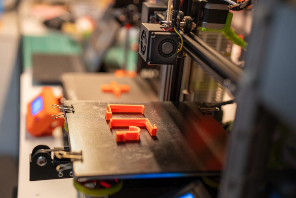
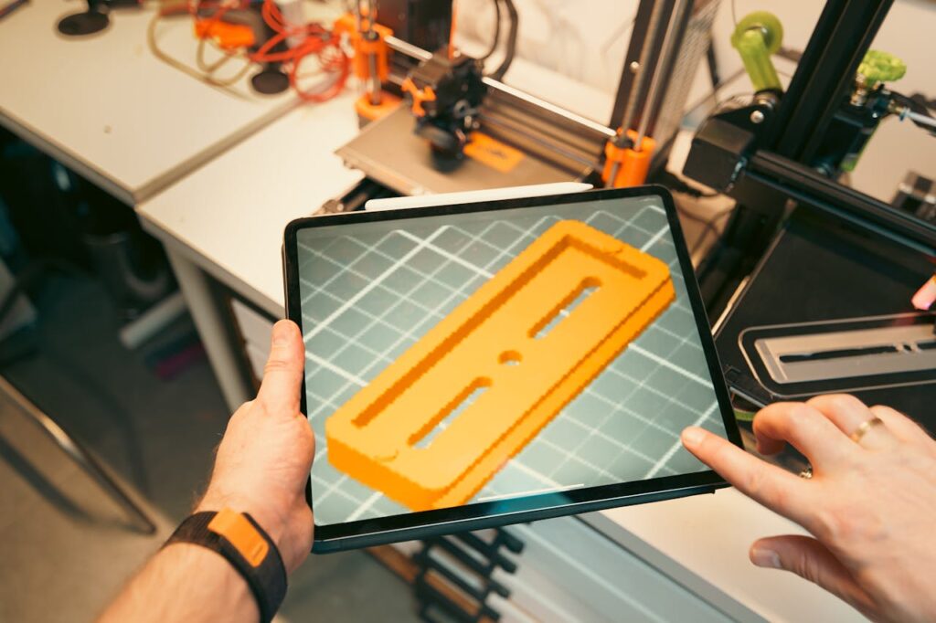
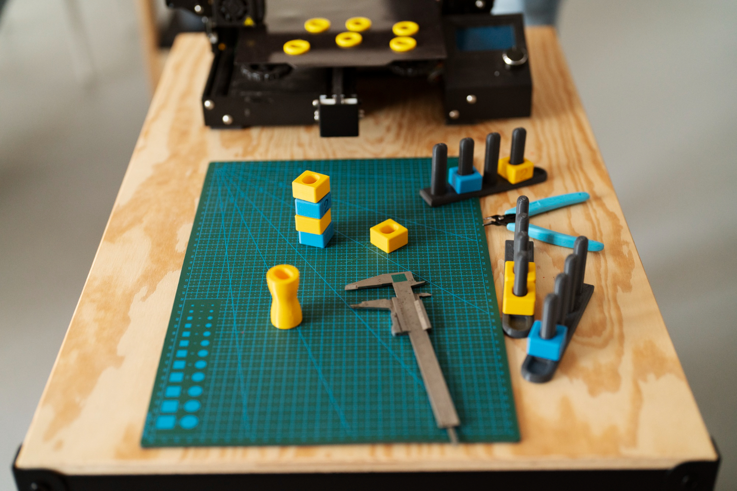
3D-printed prototypes don’t reveal draft problems the way a mold does. A printed part pops off a build plate — it isn’t ejected from steel under pressure. Engineers can carry false confidence from a successful print straight into a tooling order.
Our team reviews draft, wall thickness, and gate location before your tool is ever cut. If you want a second set of eyes on your part design before committing to hard tooling, talk to our team about your part design.
How Core-Cavity Geometry Affects Your Draft Requirements
The two halves of an injection mold don’t behave the same way during cooling. That difference matters when you’re setting draft angles.
The core is the male side of the tool — the side that forms the inside of your part. As the part cools, it shrinks onto the core. That shrinkage increases the grip between the part and the steel, which means the core side needs more draft than the cavity side to release cleanly.
A practical rule of thumb: add 0.5°–1° to core-side features beyond whatever baseline you’re using for the cavity side. The higher-risk zones include:
Deep ribs — The deeper the rib, the more surface area gripping the core during ejection
Tall bosses — Same principle; height amplifies the shrinkage grip
Hollow or cup-shaped features — These wrap around the core and are the most draft-sensitive geometry on most parts
Side actions and lifters can allow features without draft, but they add tooling cost and mechanical complexity. In most cases, applying the right draft angle is the simpler and less expensive path.
When we review parts with deep-draw core features, the draft requirement often surprises designers. A feature that looks straightforward in CAD can need significantly more taper than the baseline once you account for material shrinkage and surface texture on the core side.
Surface Finish, Texture Specs, and the Draft Angle Math
Surface finish and draft angle are connected. The rougher or more textured the surface, the more draft you need — and the math is specific enough that guessing will cost you.
SPI surface finish grades run from A-1 through D-3. Here’s how draft requirements shift across that range:
A-grades (A-1 to A-3) — High polish; can sometimes run at 0.5°–1° on smooth geometry
B-grades (B-1 to B-3) — Semi-gloss and satin finishes; typically 1°–2°
C-grades (C-1 to C-3) — Matte finishes from stone or paper media; 1.5°–2°+ depending on depth
D-grades (D-1 to D-3) — Rough, blasted finishes; 3°–5° or more depending on texture depth
Texture depth is measurable. Your texture vendor can give you the exact depth spec for the grain you’ve selected. Get that number before you finalize your CAD model — not after.
Mold direction matters too. Texture on a surface that runs parallel to the direction of pull is the most draft-sensitive zone on your part. That’s where drag marks show up first if draft is insufficient.
The safest approach is to align your draft spec, texture spec, and resin shrink rate in a single DFM session before tool release. Resolving all three together prevents cosmetic defects that pass ejection but fail visual inspection on the production floor.
Ready to move from design to production?Contact Freeform Polymers today!
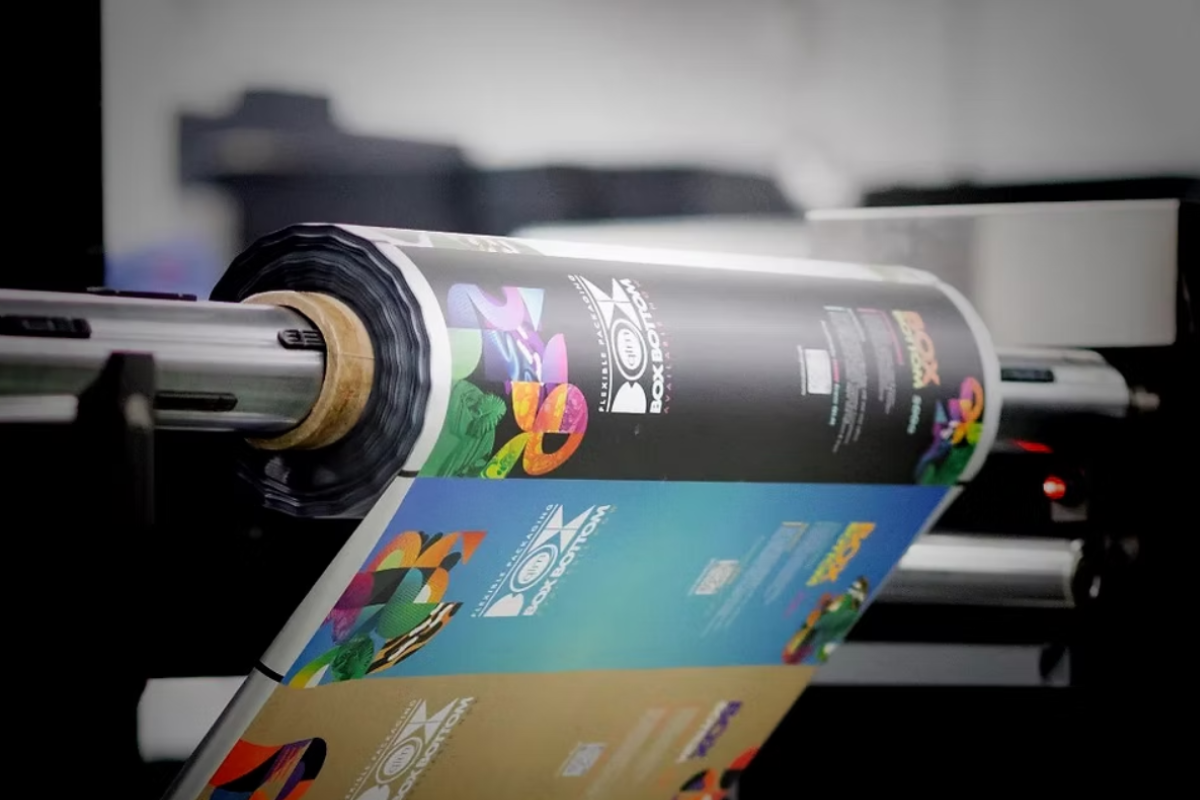
Does your part need a full-color logo, barcode, or photo-quality graphic? You may wonder if your manufacturer can even print that in-house. At Freeform Polymers, we use digital printing to…
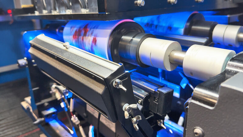
What actually happens when a machine prints a full-color logo onto a curved plastic part, with no plate and no setup delay? That question comes up a lot when customers…
A curved enclosure or textured housing can be hard to print on cleanly. This is exactly the kind of job pad printing was built for. Every day, we help customers…
Does your part need a simple logo, or a full-color image? That one question decides whether pad printing or digital printing is right for your part. At Freeform Polymers, we…
Injection molding is precise and repeatable. But it still has real limits on size, design, tooling, and time. At Freeform Polymers, we know plastic molding works within the size of…
Design mistakes are one of the most common reasons a first mold sample gets rejected. A part looks perfect on screen. Then the sample comes back warped, or a thin…
Before hot plastic fills a mold, it starts small and simple. It begins as tiny pellets, about the size of rice. So what are those pellets made of? And what…
Not every plastic can go through an injection molding machine. Not every part shape can, either. You might have a design ready and a plastic in mind. Then a shop…