Injection Molding Limitations: What They Mean for Your Part Design
Justin Brown
July 9th, 2026
Injection molding is precise and repeatable. But it still has real limits on size, design, tooling, and time.
At Freeform Polymers, we know plastic molding works within the size of the machine, the rules of good part design, and the mold itself. Knowing these limits before you finalize a design saves time and avoids costly changes later.
This guide walks through four limits you’ll run into: part size, design rules, tooling trade-offs, and lead times. Each section explains what causes the limit and how to design around it.
What Are the Limitations of Plastic Molding?
Plastic molding has four main technical limits. Knowing them helps you plan a smarter part design.
Size. Machine tonnage and mold size set an upper limit on how big a part can be.
Design. Wall thickness, draft angles, and undercuts all affect how well a part molds.
Tooling. Ejector pins and cooling lines can leave marks or slow down each cycle.
Lead time. Building a mold adds weeks before the first part comes off the line.
Size Limitations in Injection Molding
Every injection molding machine has a size limit. That limit is called tonnage.
Tonnage is the clamping force that holds the mold shut during injection. Machines typically need 2 to 8 tons of force for every square inch of your part. The exact number depends on your material and part shape.
Bigger parts need bigger molds. Bigger molds need bigger, more expensive machines to run them. Some parts are simply too large for standard production equipment, or too costly to justify.
Manufacturers typically compare part size to available press tonnage before quoting a project. This step confirms early whether a design is a strong fit for standard equipment.
Watch for these signs your part may exceed standard tonnage:
Your part is larger than a typical car dashboard panel.
Your design needs a mold bigger than most standard press beds.
Your quote comes back suggesting a split mold or multiple parts.
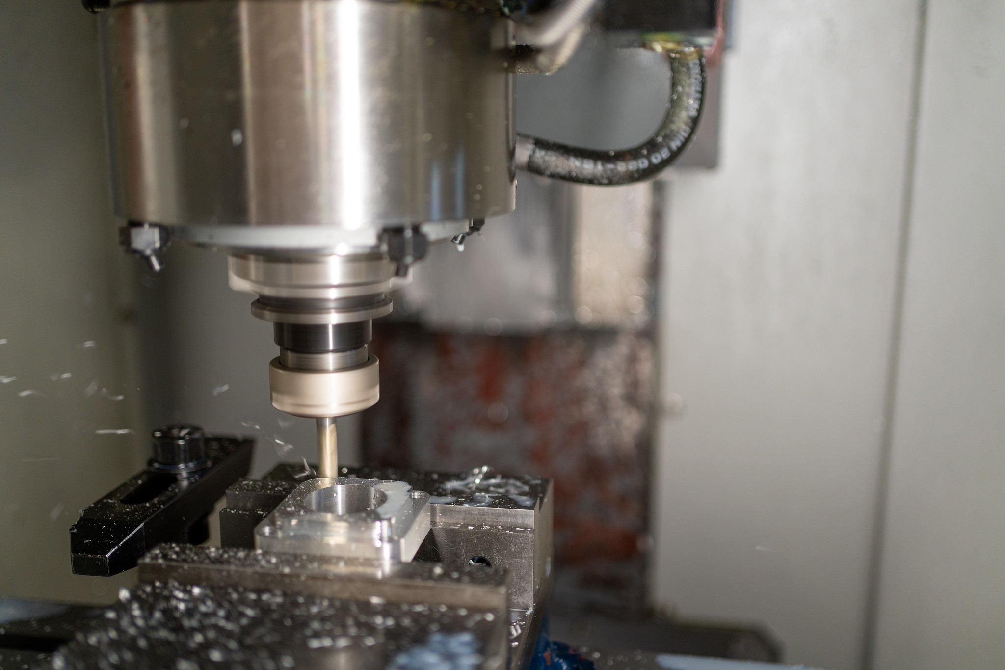
If any of these apply, another process like large-format 3D printing or CNC machining may fit better.
Size sets the outer boundary. But even a part that fits the press still has to survive its own design.
Design Constraints You Need to Plan For
Good part design prevents most molding problems before they start. Three rules matter most: wall thickness, draft angles, and undercuts.
Wall thickness should stay even across your part. Thick spots cool slower than thin ones. This uneven cooling causes warping, sink marks, and weak spots.
Draft angles let the finished part release from the mold. Without enough draft, the part drags against the mold walls on ejection. This can scratch the surface or damage the part. Our draft angle guidelines walk through how much draft your part may need.
Undercuts are shapes that block a part from pulling straight out of the mold. They require extra mold features like slides or lifters. These add cost and complexity to your tooling.
Keep these design rules in mind:
Aim for uniform wall thickness throughout the part.
Add at least 1 to 2 degrees of draft on vertical walls.
Avoid undercuts where possible, or plan for added tooling cost.
Round sharp internal corners to reduce stress points.
Once the design is locked, the mold itself introduces a new set of trade-offs.
Ejector Pins and Cooling Lines: The Tooling Trade-Offs
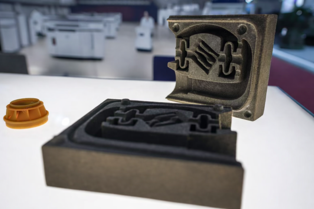
Every mold uses ejector pins to push your finished part free. These pins press against the back of the part during ejection.
This pressure can leave small round marks on the part surface, a common feature of the injection molding process itself. Most marks are minor and sit on hidden or non-cosmetic surfaces. Pin placement is planned around your part’s visible faces whenever possible.
Cooling lines run through the mold to pull heat out of the plastic. Where these lines sit affects how fast a part cools and how evenly it shrinks. Poor cooling line placement can cause warping or add time to each cycle.
Cooling channel layout is typically reviewed before a mold is cut. This step catches uneven cooling paths that could slow production or hurt part quality.
Limitation
Typical Visible Effect
Design Mitigation
Ejector pins
Small round marks on the part
Place pins on hidden or non-cosmetic surfaces
Cooling lines
Warping or longer cycle times
Review channel layout before cutting the mold
Once tooling decisions are set, they shape one more factor buyers usually underestimate: time.
Lead Times: Why Injection Molding Isn’t a Same-Week Solution
A new mold takes time to build. We can turn a steel mold for a simple part around in just under two weeks. More complex designs can take up to 6 weeks.
This mold-build time happens before your first production part exists. Once the mold is done, production itself moves fast. Parts come off the line in seconds to a few minutes each.
Early design input can shorten your mold-build timeline. Locking in your design details before we start cutting steel avoids delays later.
If you need parts faster than a mold allows, short-run or prototype options may fit better. These skip full steel tooling for a quicker turnaround on smaller quantities.
Ready to talk through your design and timeline? Contact us or call at (435) 774-9090 to get started with your project’s design today!
If you’ve gotten quotes from two injection molding companies, you may have noticed something. One mentions a hydraulic machine. The other mentions an electric machine. You might wonder if that…
Combining metal with plastic takes a different process than adding a soft grip to a hard plastic part. Both are common in insert molding and overmolding, but they solve different…
Not all injection molds are built the same way. At Freeform Polymers, we’ve seen how the type your part needs can change your tooling cost by thousands of dollars. That…
Ever gotten a design review back with a flag that says “insufficient draft”? You had no idea what that meant. It’s one of the most common notes molders give on…
You have a part idea. You don’t know what it will cost to make. That’s the moment most first-time customers reach out to us at Freeform Polymers. They want to…
Not every large plastic part belongs in an injection mold. Some warp during cooling. Some cost more to tool than the finished part can justify. And some simply won’t fill…
Plastic injection molding feels like a modern industry. But it’s over 150 years old. The first machine was patented in 1872, decades before plastic became a household word. If you’ve…